- 16f628a Simple Programming Language
- 16f628a Simple Programming Instructions
- 16f628a Simple Programming Manual

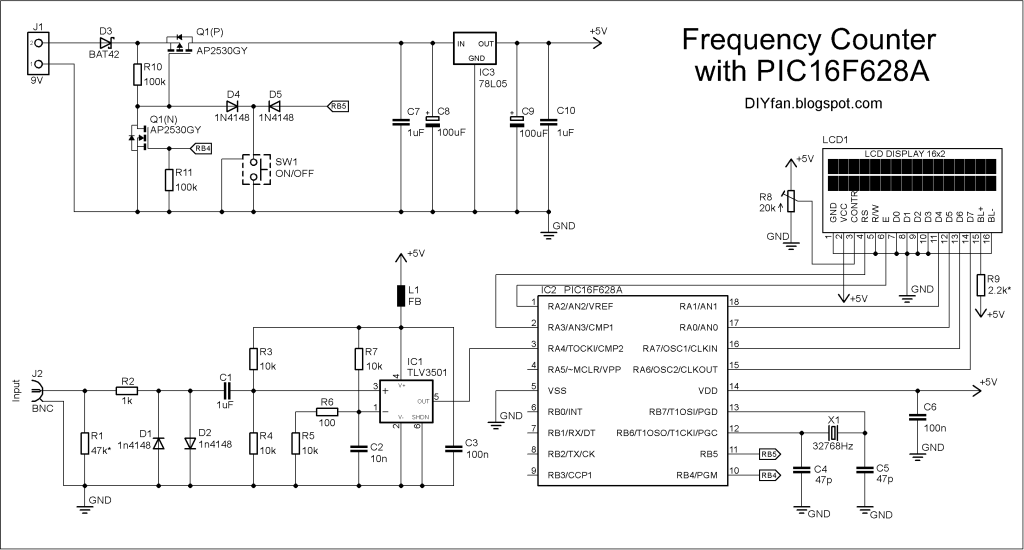
Here’s another breadboard module that carries a PIC16F628A microcontroller. The power supply pins and the I/O ports of the PIC16F628A microcontroller are accessed through male headers. It can be easily plugged into a breadboard and is very useful for quick prototyping. It frees up a lot of space on the breadboard since the oscillator, reset, and ICSP circuits are already built on the module. It is different from the previous PIC16F688 breadboard module in the way that the microcontroller now runs with an external 4.0 MHz crystal. So, this module will be more appropriate for experiments that require accurate timing calculations. Besides, the PIC16F628a microcontroller allows you to read/write 8-bit data directly through PORTB, which is 8-bit wide (none of the ports in PIC16F688 were 8-bit wide).

I've got the PIC 16F628a on a breadboard in a simple circuit. The power pins are connected, and a resistor and diode connect MCLR to the power supply but don;t allow the 13volt programming voltage back into the circuit. I powered the circuit with 5volts and will program/read the pic at 5volts.
- It would really be a good idea to go with the 16F628A as it's not just straight forward as plugging the chip onto a board and then programming it, with using a breadboard it gets you used to what pins you need.
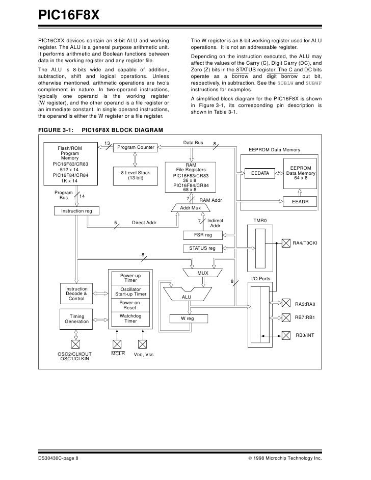
- Cycle, except for program branches (which require two cycles). A total of 35 instructions (reduced instruction set) are available, complemented by a large register set. PIC16F627A/628A/648A microcontrollers typically achieve a 2:1 code compression and a 4:1 speed improvement over other 8-bit microcontrollers in their class.
- When the 16F628A is erased, all the lines will read 0x3FFF. The actual code you are writing doesn't matter at all when programming with the pickit2. In the pickit2 software, you can erase the 16F628A, set a few lines to something that isn't 0x3FFF, and click on 'write'. That should be enough. If you read it back, it should be the same.
The layout and the circuit diagram of the module is shown below. The module has ICSP header pins for in-circuit programming, a reset switch, and an LED as power-on indicator. It provides easy access to all the pins of PORTB, and RA0 through RA4 pins of PORTA. Pins RA6 and RA7 are used for external crystal connections, whereas RA5 is input only pin and is used for reset circuit.
This circuit can be soldered on a general-purpose prototyping circuit board. Here are some pictures that I took of my finished board.
Now, the breadboard module is ready and its a time to test it. I have written a small application program to chase 8 LEDs that are connected to the PORTB pins of the PIC16F628A microcontroller. The circuit diagram is not shown here as it is very simple. The anodes of the 8 LEDs are connected to the PORTB pins, whereas the cathodes are grounded through 330 ? resistors in series. The program is written in C and is given below. I compiled it with MikroC Pro for PIC, and loaded the HEX file into the PIC16F628A microcontroller with my handy iCP01 USB programmer from iCircuit technology. In the configuration bit settings, MCLR should be enabled and the clock source could be XT or HS, both will work for 4.0 MHz.
16f628a Simple Programming Language
Here is the test program in MikroC.
16f628a Simple Programming Instructions
After the program is loaded, turn the power ON and watch the chasing LEDs.